ACO Drain
|
 |
|||||||||||||||||||||||||||||||||||||||||||||||||||||||
hh
|
||||||||||||||||||||||||||||||||||||||||||||||||||||||||


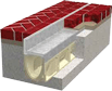
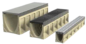 300mm internal width
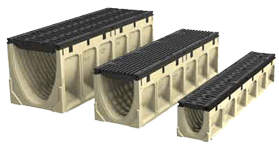 300mm
internal width
300mm
internal width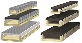

 TECHNICAL SUPPORT
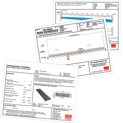
  ‘Hydro’ is a purpose written, hydraulic design program modelled on differential calculus for
 of minimum 'freeboard' (gap between the underside of grate and the top of liquid in trench). |
capacity of the channel run. (14.75 l/s from example below) |
Grate Hydraulics - Project specific grate intake calculations to provide grate catchment data
TO REQUEST THIS SERVICE, CLICK HERE
 ACO has independently measured, by experimentation, the hydraulic intake capacities of ACO Drain grates. Tests were carried out under varying flow rates and catchment approach slopes. To determine the hydraulic utilisation, each grate was tested until bypass occurred (point at which liquids would pass across grate).
The Grating Intake Calculator (GIC) provides information on the intake efficiency of the chosen grate. If the required liquid intake is greater than the grate’s performance, the extent of bypass (or failure) will be calculated. (click here for more info)
To generate results from the ‘GIC’ program the following information is required:
- Length of trench run (metres)
- Length and width of catchment area (metres)
- Position of trench in catchment area
- Surrounding pavement/surface type, e.g., concrete, asphalt, etc.
- Rainfall intensity (mm/hr)
- Perpendicular approach slopes to trench (%)
- Preferred grate type
Results are provided either electronically (PDF) and/or in printout format.
'GIC' plots shows:
geometry and hydraulics |
approaching grate |
grate information |
area per metre of trench run |
Run Layout Scheduling - Plan and profile layouts complete with bill of materials
TO REQUEST THIS SERVICE, CLICK HERE
 CAD Design Service
ACO can provide a cost-effective surface drainage solution to satisfy a project’s design requirements. Trench drain layouts will be designed to take full advantage of existing and proposed site grades, utilising existing services where possible.
In order to produce a plan layout, the following information is required:
- Plan of site showing elevations
- Existence of any depth restrictions
- Position and type of any plumbing fixtures/outlets
- Position of any permanent structures
- Liquid flow pattern and type of traffic (including traffic flow)
Results provided are:
- Plan layouts (CAD) showing the trench drain positions relative to site structures
- Installation drawings and specifications
CAD printout provides:
Download details for all products, loadings and pavements at www.acoaus.com.au/ |
 |
|||||||
 |
||||||||
ACO SchedulerACO has written a proprietary software program, ‘Scheduler’, that shows trench drain runs in profile. The program automatically plots each run showing positions of accessories, outlets, junctions, etc. It automatically calculates a ‘Bill of Materials’ for each run and totals multiple runs to ensure the correct amount of parts and pieces are ordered. ‘Scheduler’ plots are particularly useful for installers. Results (CAD) provided are:
|
|
'Scheduler' plot provides:
|
|||||||||||
Ponding Analysis - Risk analysis of flood situations, including estimated flood size and duration
TO REQUEST THIS SERVICE, CLICK HERE
 Temporary ponding is a short lived flood situation, which, in some circumstances, can be tolerated allowing an intentionally undersized trench drain system. It allows a more economical system to be used that will work effectively under most weather conditions, but will be slightly under designed for heavy storms.
Ponding analysis should only be considered where buildings and property are not in close proximity to the drainage system to minimise risk of damage. It is an ideal option for the outer areas of large parking lots, distribution yards, etc., (Risk Analysis).
The ponding analysis map shows the size and duration of the flood.
In order to produce a ponding analysis, the following information is required:
- Full information required to run the 'Hydro' plot
- Plan of site showing elevations
- Existence of any buildings
- Perpendicular approach slopes to trench (%)
Results provided are:
- Plot showing extent of ponding: width and depth
Ponding analysis shows:
discharge |
size and type |
temporary ponding |
worst ponding scenario |